Starter motor analysis
Starter motor analysis
A Detailed Introduction to Starter Motors
I. Overview of Starter Motors
A starter motor, also known as a starter, is the core executive component of an internal combustion engine’s starting system. Its primary function is to convert direct current electrical energy from the battery into mechanical torque, driving the engine flywheel to rotate. This completes the initial cycles of intake, compression, ignition and exhaust, bringing the engine from a stationary state to self-sustaining operation.
It is a high-power DC motor designed for short-time duty cycles, with an operating current ranging from 100 to 600 amperes. A single operation normally lasts no more than 5 seconds. Characterized by high torque at low rotational speeds, it is an indispensable key component for internal combustion engine equipment including passenger vehicles, commercial construction machinery and generator sets.
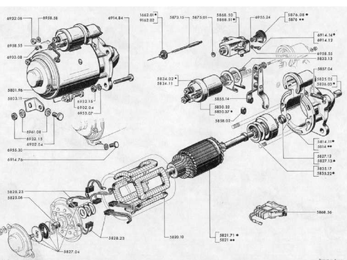
II. Core Structure of Starter Motors
A standard starter motor consists of three major assemblies: the DC electric motor, transmission mechanism and electromagnetic switch. These components work in tandem to complete the full cycle of gear meshing, power driving and gear disengagement.
(1) DC Electric Motor (Power Core)
It adopts a series-wound DC motor, where the stator windings and armature windings are connected in series. This design delivers maximum torque the moment the motor starts, while torque naturally drops as rotational speed rises, preventing damage to the starter from reverse driving after the engine fires up.
- Stator: Composed of excitation coils or permanent magnets and the motor housing, it generates a fixed magnetic field. Field-wound stators feature high power density, while permanent magnet stators are compact and energy-efficient.
- Armature (Rotor): Made up of iron core, windings and commutator. When energized, it rotates under magnetic force to output torque.
- Brushes and Brush Holders: Constructed from graphite, they supply stable electric current to the armature and require timely replacement once heavily worn.
- End Caps and Bearings: Support the rotor, maintain rotational concentricity and reduce frictional loss.
(2) Transmission Mechanism (Meshing and Clutch Assembly)
Its core components are an overrunning clutch paired with a drive pinion, enabling one-way torque transmission and protection against reverse rotation.
- Drive Pinion: A small-module gear that meshes with the engine flywheel ring gear to transfer torque.
- Overrunning Clutch: Locks during cranking to transmit torque from the starter to the flywheel. Once the engine’s rotational speed exceeds that of the starter, it slips automatically to avoid burning out the starter due to high-speed reverse driving.
- Shift Fork and Return Spring: Driven by the electromagnetic switch to push the pinion into mesh; the spring pulls components back to disengage the gear after startup.
(3) Electromagnetic Switch (Control Core)
It acts as the master switch of the starting system, serving two critical roles: controlling heavy current with low current and performing mechanical actuation.
- Pull-in Coil and Hold-in Coil: Generate electromagnetic force when energized to pull the plunger forward.
- Plunger and Contact Disc: The plunger pushes the shift fork to engage the pinion; simultaneously, the contact disc closes the main contacts to connect the heavy-current circuit between the battery and the electric motor.
- Return Spring: Releases electromagnetic force once power is cut off, resetting the plunger, drive pinion and contact disc to their original positions.
III. Working Principle of Starter Motors (Step-by-Step Breakdown)
Taking a 12V automotive starting system as an example, the operation process is divided into four stages:
- Ignition Switch Activation: The ignition key is turned to the crank position. Low current flows through the starter relay into the coils of the electromagnetic switch.
- Electromagnetic Actuation: The pull-in and hold-in coils create a magnetic field, pulling the plunger forward. The shift fork pushes the drive pinion to mesh with the flywheel ring gear.
- Main Circuit Closure: Once the plunger reaches its forward travel limit, the contact disc closes the main power contacts. Heavy current flows into the motor, spinning the rotor at high speed and turning the engine crankshaft.
- Reset After Successful Startup: Once the engine ignites and runs independently, the ignition key is released to cut power to the electromagnetic switch. The plunger and pinion retract under spring tension, the main circuit opens, and the starter stops working.
IV. Main Classifications of Starter Motors
Based on structural design and technical routes, starter motors fall into three categories for different vehicle types and operating conditions:
(1) Field-Wound Starter Motors
The traditional mainstream design with coil excitation stators. Low manufacturing cost and high output torque make them widely applied in commercial vehicles and construction machinery for heavy-load working conditions.
(2) Permanent Magnet Starter Motors
Equipped with high-performance permanent magnet stators, they are compact, lightweight, highly efficient and consume less power. They are primarily used in passenger cars and small gasoline engines.
(3) Reduction Starter Motors
A planetary reduction gear set is installed between the electric motor and drive pinion. A small high-speed motor generates high output torque; this design reduces overall size by 30% to 50% while significantly boosting torque. It is the mainstream configuration for mid-to-high-end vehicles today.
V. Common Fault Diagnosis and Troubleshooting
Approximately 92% of starting system faults originate from the power supply, wiring circuit or the starter motor itself. Troubleshooting follows the principle: inspect external components first, internal components later; check electrical systems first, mechanical systems second.
(1) No Response at All (No Sound When Turning the Ignition Key)
Fault Causes: Undercharged battery, oxidized or loose battery terminals, failed starter relay, open circuit in electromagnetic switch coils, broken main wiring harness.
Troubleshooting Steps: Measure battery voltage — static voltage should be no less than 12.4V, cranking voltage no less than 9.6V. Clean and tighten battery terminals. Short-circuit terminals 30 and 87 of the starter relay; if the starter runs normally, the fault lies in the relay or control circuit.
(2) Single Click Sound Only, Motor Fails to Crank or Cranks Sluggishly
Fault Causes: Low battery charge, burnt contact disc on the electromagnetic switch, seized drive pinion, damaged flywheel ring gear.
Troubleshooting Steps: Recharge or replace the battery; repair or replace burnt electromagnetic switch contacts; inspect meshing conditions between the pinion and flywheel ring gear.
(3) Weak Cranking, Low Rotational Speed and Difficult Startup
Fault Causes: Worn brushes with poor contact, short circuits in armature or excitation windings, excessive voltage drop across wiring, seized bearings.
Troubleshooting Steps: Replace worn brushes; measure winding resistance (excitation windings: 2–5 ohms, armature windings: less than 0.3 ohms); ensure wiring voltage drop does not exceed 0.5V.
(4) Free Spinning (Starter Rotates but Does Not Turn the Engine)
Fault Causes: Slipping overrunning clutch, worn drive pinion, broken shift fork, insufficient pinion meshing travel.
Troubleshooting Steps: Replace the overrunning clutch; repair or replace the flywheel ring gear; adjust pinion meshing travel.
(5) Gear Grinding Noise (Loud Metallic Impact Sound)
Fault Causes: Unsynchronized gear meshing, abnormal plunger travel of the electromagnetic switch, chipped or broken teeth on the flywheel ring gear.
Troubleshooting Steps: Adjust the push rod travel of the electromagnetic switch; replace damaged pinions or flywheel ring gears.
VI. Maintenance Standards and Operating Specifications
(1) Routine Maintenance
Regularly clean the starter housing, battery terminals and wiring connectors to avoid poor electrical contact caused by oil contamination and dust buildup.
Inspect brush wear; replace brushes when remaining length drops below one-third of the original size. Remove carbon dust accumulated on the commutator surface.
Tighten mounting bolts and wiring terminals to prevent loosening caused by vehicle vibration.
(2) Operation Prohibitions
Single cranking operation shall not exceed 5 seconds; allow a 10–15 second interval between consecutive cranking attempts to avoid coil burnout from overheating.
Release the ignition key immediately after the engine starts; do not hold the key in the cranking position for extended periods.
Never engage the starter while the engine is running, as this will cause gear impact and component damage.
(3) Periodic Overhaul
Disassemble and inspect the starter every 2–3 years or after 60,000 to 80,000 kilometers of driving. Key inspection items include overrunning clutch, bearing and gear wear, and the condition of electromagnetic switch contacts. Replace worn vulnerable parts promptly.
VII. Key Points for Model Selection and Replacement
- Parameter Matching: Voltage rating (12V / 24V), power output, pinion tooth count, meshing travel and mounting hole positions must fully match the original vehicle specifications.
- Component Quality Selection: Prioritize original equipment manufacturer (OEM) parts or reputable branded replacements; low-quality aftermarket starters suffer from insufficient torque and short service life.
- Installation Standards: Maintain a reasonable clearance between the drive pinion and flywheel ring gear. Secure all wiring connections and ensure full insulation to prevent short circuits.
VIII. Technical Development Trends
- Integration: Integrated Starter-Generators (ISG / BSG) combine cranking and power generation functions, enabling auto start-stop and energy recovery for hybrid new energy vehicles.
- High Efficiency: Permanent magnet synchronous and brushless starter motors deliver higher energy efficiency, longer service life and reduced maintenance requirements.
- Intelligence: Electronically controlled clutches achieve precise gear meshing, lower gear grinding noise and optimize vehicle NVH (Noise, Vibration, Harshness) performance.
IX. Conclusion
The starter motor serves as the “cranking heart” of internal combustion engines, featuring a compact structure and straightforward operating principles. Most starter faults stem from insufficient power supply, poor electrical contact or mechanical wear. Mastering its structural composition, working principle, fault diagnosis and maintenance techniques enables rapid resolution of starting failures, extends component service life and guarantees reliable equipment startup. Driven by vehicle electrification trends, starter motors are evolving toward miniaturization, high efficiency and integrated design, remaining an irreplaceable core component of powertrain systems.